


Buy anything from 5,000+ international stores. One checkout price. No surprise fees. Join 2M+ shoppers on Desertcart.
Desertcart purchases this item on your behalf and handles shipping, customs, and support to USA.
🚀 Amplify your signal, amplify your edge!
The HiLetgo 0.1-2000MHz RF WideBand Amplifier is a compact, high-performance LNA module designed for professional-grade RF signal boosting. With a wide frequency range, up to 32.5dB gain, and low noise figure, it enhances communication distance and signal clarity across applications like shortwave, FM radio, and cable TV. Its flexible 9-12V power input and mod-friendly PCB make it ideal for SDR enthusiasts and RF engineers seeking reliable, customizable amplification.
| ASIN | B01N2NJSGV |
| Best Sellers Rank | #62,379 in Electronics ( See Top 100 in Electronics ) #390 in Audio Component Amplifiers |
| Brand | HiLetgo |
| Brand Name | HiLetgo |
| Customer Reviews | 3.9 out of 5 stars 438 Reviews |
| Manufacturer | HiLetgo |
| Maximum Supply Voltage | 12 Volts (DC) |
| Minimum Supply Voltage | 9 Volts (DC) |
| Model | 3-01-1225 |
| Mounting Type | Surface Mount |
| Number of Channels | 1 |
| Output Power | 0.01 Watts |
| Part Number | 3-01-1225 |
| Specification Met | CE |
| Voltage | 10 Volts, 8 Volts |
T**D
Great product and would recommend to anyone that needs a preamp
excellent preamp. works extremely well on HF frequencies.
C**G
Good RF amplifier for cheap, cah be easily modified to be powered from cheap SDR dongles
This LNA is a good deal for a good and easy-to-live-with amplifier. It uses a BGA2869 as the main amplifier IC (thanks to another reviewer for the info!). One notable point is that apparently a batch of these were populated and shipped with incorrect values for the resistor that drops voltage from the 9-12V input down to the 5V that the chip requires, so check when you receive it that it has a 220 ohm resistor and has the code 221 (5%) or 2200 (1%) marked on it if you plan to power it from the VIN pad. This problem is apparently so rampant that some other product photos for other listings on Amazon actually have the wrong part visible. Note that there were some earlier revisions that have a different MMIC amp or different layout as well that have reviews included in this listing. Instead of powering it through the VIN pad, this PCB's real party trick is that it can be modified to be driven from a 5V bias T voltage from the receiver that many SRD dongles (like the RTL-SDR v3 and v4) can provide with only a piece of resistor leg or jumper wire, requiring no outside power supply. Just solder a jumper from the center RFout pin on the SMA connector to the node that connects to the Vcc pin on the IC, as seen in the photo. The bias T option can be easily enabled in most SDR software like SRD# or SDR++. The LNA draws around 25mA and the RTL-SDR is rated to source 180mA. I also included screenshots of SDR++ tuned to a weak broadcast FM station using the dipole antenna kit offered with the RTL-SDR v4 so that you can see the gain difference. The only difference between the two screenshots are with the LNA included and removed from the coax line. You can see the difference between the waterfall graphs on the screenshot with the amp removed, and can see the difference on the SNR meter on the top right between the two. Note that both input and output on this amp are female, so you'll need a male-to-male SMA adapter to connect it in-line with this antenna kit. Overall, this is a nice amp for a good price, the PCB is laid out well with good via fencing for RF signal integrity, and has a fair amount of vias to thermally connect the chip to both the top and bottom ground plane for cooling.
B**9
A tricky device. Things you should know.
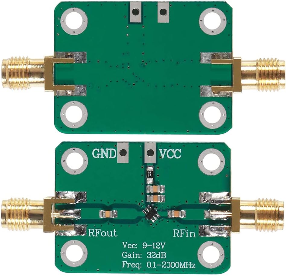
This preamp works fine, but I think you have to apply it correctly. It's a GaAs Rf amplifier chip, similar to unit such as the Avago 82563, but not that -- possibly a Chinese clone or variant of a different chip. This one appears to run with a current of about 35 ma to deliver its full gain, and is intended for 5V operation. The sellers have adapted it to run at 9-12 volts by adding the 220 ohm resistor, to drop the voltage down. If the voltage is reduced too much, its gain goes down. In fact, this is a good way to make a variable gain preamp - by driving it with different voltages (without a dropping resistor), say between 3V and 5V. At the lowest voltages, it actually becomes an attenuator. Of course, the current consumption is fairly high for that application -- you might do better in your attenuator circuit by just using a PIN diode. The 220 ohm resistor permits full output when connected to 12V, but at 9V the gain will be much less, which may be why some reviewing it here have had mediocre results with it. If you intend to use it at 9V, you best reduce the resistance. In my application, using two Lithium Ion batteries (3.2-4.2V each) I found a good choice was to change the 220 ohm resistor to 120 ohms. However in my circuit, I also added a 1 mH choke as shown, which has 33 ohms series resistance, so my resistor is actually 100 ohms. The lower the voltage you run it from, the more the inductor is necessary for best output. Check that it is drawing at least 25-35 ma. Also note that it's good to mount the unit in a grounded metal box. Traditionally, the hobbyist mounts these kinds of devices inside an Altoids tin. In my case I used some copper tape lining inside a plastic box. The seller has stripped down their product here to the bare minimum, and I think they could have done a better job making it usable over a wider voltage range. But with care, it will give excellent results. I have two cautions. First, don't try to run this from 5V -- unless you make the modification I suggest (small resistor + RF choke). Second, be careful soldering around this, because GaAs circuits die very easily when treated roughly. If you're not comfortable making changes to the circuit, perhaps it would be better to get one of the other units. Or, get a transistor-based (Jfet) preamp. Those would be more costly, though. Only the very low cost justifies this circuit.
T**K
Optimism Fail
I am usually skeptical of negative reviews but I had high hopes for this amplifier even though my optimism was not deserved. I needed a small preamp for a shortwave receiver I am building. I have already built my own preamplifier but I wanted to purchase a commercial one to compare my homebrew one against. I soldered power wires onto the board and hooked it up to my oscilloscope and tracking generator and swept from 0 to 30 MHz. The Bode plot showed no appreciable gain across the spectrum. I get the same response from the amplifier whether power was applied or not. Looking at the power output of my lab grade power supply, it showed it was consuming 0.00 watts. It should show even a small amount of power being consumed. The power supply can show the power usage all the way down to a 100th of a watt. Seeing no power being used was a very bad sign. Next I pulled out my magnifying glasses and started probing around on the board. There are a total of 6 components on the board (excluding the SMA connectors). When I touched the IC in the middle, it wiggled. I inspected it further and saw that the right hand side was not soldered to the board. I pulled out my soldering iron and reflowed solder on all the ICs pins and the other 5 components as well. I really thought that was going to fix it but nope, still no gain. It is possible that I just got a bad one and maybe others will have better luck, but I am a little disappointed to say the least. I don't even feel like dealing with the hassle of trying to return it. I will just accept the loss and see it as a fun little $10 experiment on a Saturday morning.
N**Y
Great match for the RTL-SDR
This amplifier is perfect for increasing the reception of an RTL-SDR dongle. It just about covers its entire tuning range, and then some. I've mainly been using it for shortwave where it has dramatically increased the number of channels received. It's also proven itself well on FM (just don't overdrive the SDR frontend!) and other bands. Just one caveat: you'll need to BYOP (Bring Your Own Power) as its DC-blocking capacitors prevent it getting power from the coax. A nine-volt battery should do the trick however. Interestingly enough though, the amplifier ("N02" INA-02186 perhaps?) is designed to take bias-T power on its output pin (7V max), meaning that those adventurous enough to make some slight modifications might just be able to power the amplifier straight from the RTL-SDR! As mentioned before, this amplifier performs quite well and can in fact attain its advertised +30dB gain. However, do note that, like any other LNA, it will amplify the noise floor somewhat as well. In summary, this amplifier is ideal for anyone wanting an inexpensive upgrade for their RTL-SDR.
D**E
Real Measurements - Works Per Datasheet
I tested the product versus the HP specification for the chip used, the HP INA-02186. The datasheets are available online. The forward gain, input and output VSWR are within the HP spec. I measured 31.5 db gain to 1GHz at 35 mA bias. The reverse isolation is measured at -33 db at 1 GHz. This product PCB implementation is on 62 mil FR-4, though in the datasheet HP does not recommend using thicker than 32 mil, which may account for the higher S12. The noise figure measures below 4 db at 1GHz, which is a limitation of my equipment. This data was taken without external shielding, which may also account for higher S12. The circuit implementation itself is fairly close to the HP recommended board design, using a 178 ohms (measured) load resistor and a choke (2 ohm dc). As such, the amplifier is self biased, and achieved 35 mA bias with 11.45 v board terminals and a measured 5.13 v across the INA device. The board assembly is clean. A simple soldered cover might help in various LNA applications, as there are available from other sources for a few more dollars. The main issue with this product is that it is NOT a 2000 MHz amplifier as RF amplifiers are specified. HP in its datasheet calls the INA-02186 a "3 db Bandwidth: DC to 0.8 GHz". As a narrow band amplifiers, as many reviewers seem to be intending, the amplifier will deliver some gain.
K**P
Be prepare to make some repair, poor QC
I got this from Amazon warehouse deal. The device was dead on arrival. I have two points here, - There seems zero quality control at mfg level. I spend good amount of time figuring out why this is not working. turned out, there was a wrong resistor (2200 ohm instead 220 ohm) placed in the circuit. So, basically it was not getting enough supply to operate. See the picture. There seems to be one more review with similar issue so seems like a whole batch may have this issue. - Amazon should not resell such returned item without proper testing. For Electronics, physical inspection is not enough and I am sure the buyer who returned this before must have returned with not working status, so why it was sent to me without testing first. The new item should not need repair to start working out of the box. After putting 4.5v supply bypassing the resistor, the amplifier started working well. It seems do reasonably well in keeping noise low and amplification is adequate to work with my loop antenna. If you are buying this item, I recommend to inspect thoroughly before powering up.
D**N
Lots of gain!
I bought this amp to boost the signal level from my small receiving loop antenna for Amateur Radio. I use that antenna as a noise source for my MFJ 1026 Noise Cancellation unit. I had a 10 dB preamp on there before, and it just didn't provide enough noise for the MFJ to work effectively. With this unit, I can amplify the noise to the point where it's even louder than the main antenna, even with the built-in preamp in the MFJ turned off. The MFJ now cancels all of the noise from my immediate neighbor's house almost totally. I am powering the from an old 6VDC wall wart that puts out 9V with this minimal load. This is probably the best $10 I ever spent.
F**O
prodotto molto valido preamplificatore d'antenna per le HF validissimo.
Prodotto usato come preamplificatore HF in un ricevitore FT-277 che normalmente non ha di preamplificazione. Segnali passano da 3 a 8 e basso rumore di fondo. Consigliato. Pilotato con alimentazione tramite potenziometro da 500 ohm in serie è possibile variare il livello di amplificazione ma non solo, diminuendo la tensione si ottiene una attenuazione del segnale in ingresso. In pratica variando la tensione si passa in continuità da amplificatore ad attestature. Occhio alla schermatura, è facile ottenere inneschi a motivo dell'elevato fattore di amplificazione. Io l'ho chiuso completamente in una scatoletta di lamierino completamente saldata. Allego toto del montaggio e della scatoletta variatore di tensione.
U**L
AT LAST one that works
I've tried a few of these cheap Chinese preamps and most suck, but this one boosts the signal (and noise of course) from both tuned shielded receive loops and untuned loops on topband and 80m, allowing me to phase receive antennas against my main transmit antenna (3/8 wave inverted Ls on those bands) and null out local interference - or to phase receive antennas against each other. Obviously they work better right by the loop. I used a 12v supply with them. The actual noise figure of the amp itself isn't something I can test.
F**O
Amplificatore 0.1- 2ghz
Il mio non funzionava restituito . Alcuni dicono che e' errata la resistenza da 2,2 k, infatti sostituita correttamente con 220 ohm tutto ok
S**C
Works well.
Works well. Using on 137mhz ( Pi SDR server) & 156/7mhz (traditional scanner). I do have an FM band stop filter fitted before the amp. Fast dispatch. Recommend.
L**N
Does work
I have only so far used it on HF below 30mhz and it does pull up the signal, however it also lifts the noise, when using a 9v battery there is a big drain in battery. I bought a voltage dropper which dropped the 12v Motorcycle battery down to 9v, i then ran the unit for 24 hours receiving FT8 signals on my SDRplay and hardly any voltage drop. I haven't yet used it on 1090mhz as another buyer did but intend to do that quite soon, all in all worth the money.
Trustpilot
1 month ago
2 days ago