


Buy anything from 5,000+ international stores. One checkout price. No surprise fees. Join 2M+ shoppers on Desertcart.
Desertcart purchases this item on your behalf and handles shipping, customs, and support to USA.
⚙️ Amplify your control, power your projects — the MOSFET module that means business!
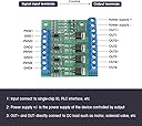
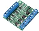
The Hilitand 4-Channel MOSFET PWM Driver Module delivers stable, interference-resistant amplification of PWM signals with a robust 10A output capacity. Designed for controlling motors, LEDs, solenoids, and more within a 3.7-27V DC range, it features full input-output isolation via high-quality optocouplers and intuitive indicator lights. Compact and easy to install, this module is ideal for professional and industrial automation projects seeking reliable, precise power control.


| ASIN | B07QGXY7F3 |
| Brand Name | Hilitand |
| Customer Reviews | 3.9 3.9 out of 5 stars (139) |
| Item Dimensions | 2.17 x 1.97 x 0.39 inches |
| Manufacturer | Hilitand |
| Maximum Supply Voltage | 20 Volts |
| Minimum Supply Voltage | 20 Volts |
| Model | YYNMOS-4 |
| Mounting Type | Surface Mount |
| Number of Channels | 4 |
| Output Power | 1080 Watts |
| Package Type Name | small box |
| Supply Current | 10 Amps |
| UPC | 748018565745 |
| Voltage | 27 Volts (DC) |
H**T
Excellent and effective
This product performs exactly as expected. I used it to amplify pwm signals from a PLC to operate hydraulic solenoid valves in a project I have been working on. This replaced very expensive proportional solenoid valve controllers, and it works well.
R**R
NOT A 3.3V INPUT
Beware that you need to hack the board to make it work with 3.3V devices, such as ESP32. The PC817 optocoupler input has both 4K7 resistor and 1.6V LED connected in series. With 3.3V input that results in optocoupler input current about 0.36 mA - too low. One way to make this work is to replace 4K7 resistor with 510 Ohm resistor. Which results in optocoupler input current about 3.3 mA.
B**9
must be over 3.9V input to function
As others have posted here, these work well if you have a trigger voltage over 3.9V, these will not work with an input voltage less than that which is posted incorrectly in the description. I knew this ahead of time because a co-worker bought theses and sent them back because of it. I only use a 5V input so these work fine. It would be nice if there was another mounting hole on the side opposite the 2 holes. For the cost though, it's a very cheap alternative to making your own board.
G**F
Definitely works well.
I used these for work for testing mechanical switches. Used two of these FETs to drive 1 million solenoid closures to test some handle bar switches. Ran for days start to finish with no issues.
J**A
Complete BS!
I'm not new to these but they've changed them and now they won't work with 3.3v logic. I should t have to modify it and remove led's and short out connections to make it work at the specs it's advertised to work at! People/sellers whi pull this crap need removed from here. Do not modify these to make them work and let these sellers off the hook! Send this false advertisement garbage back and make them eat the cost!
C**.
Input voltage of 3 volts is incorrect. Shorting the input LED is a fix for 3.3v PWM input.
Like others I didn't read fully through the reviews. This device does not work with a 3.3v pwm input such as that from and ESP8266. Shorting the input LED as suggested by others does allow for control from the ESP 3.3v pwm output. Still, I wasted a lot of time and effort troubleshooting the device, only to find out that it was not spec'd correctly. It is a good value and performs the needed task, but the product needs to be described correctly. I wonder if this is not an issue with the "old" design, which the vendor is shipping concurrently.
A**N
Pay attention to the modifications to make this work
To make this switch properly the led had to be removed and jumpered for it to work with 3.3v of micro controller. Fairly easy but your working with small components
M**R
Finally! A 5V to 12 V interface!!
So I am going to give it five stars for now. I am running a test to see if the Mosfets get hot or not running an automotive 30 amp relay coil. So far the board is ice cold!! Ive been writing code and developing systems around Arduino and Raspberry pi controllers. This is first interface I have found that can run an automotive type relay. The only thing on market are relay boards with non removable relays. This is stupid to run a relay to power a relay. The relays on these boards are only capable of 10 amps and if any one of the relays go bad the inter board is junk unless you can solder a new one in place. 10 amp relays are not enough for general use, you need a relay capable of twice the load of what ever you are trying to run. Most automotive hardware is 8 amps. The relays on these junk boards are not adequate, you need to use the wimpy relays on these boards to signal a real relay with generally 30 amps. Now you can power something directly from a 5 volt logic controller!! So far this board looks good. Its build quality is very solid, it shipped to me very fast. I was surprised how fast it got here. To the vendor do not ever discontinue this product! Please expand this to an 8 channel and even larger. Get us shields that will plug into an Uno R3 Please. This is the interface we are all looking for not weak non replaceable relay boards.
P**K
I needed a solidstate relay to isolate my 3.3v MCU from D12 220AC 40amp relays. This board worked great for my application. Each channel is isolated independently so needs both + and - wiring. One thing to Note: my MCU is exactly 3.3v and the power drop across the first Blue LED is significant enough to prevent the MOSFET from actuating. I'd suggest wiring with 5v MCU. However, I removed the (low voltage side) blue LEDs and bridged the pads with solder. And then it worked.
F**O
Como ya se comento; para hacer que funcione hay que eliminar el led azul y hacer un puente. Adicionalmente, también tienen fuga a tierra por lo que si conmuta un pequeño voltaje aprox 1.6 volts estando en reposo. Habría que revisar el modelo mas nuevo. Si te llego el modelo anterior regresalo.
A**Y
I want to caution you: if you are using these on 3.3V using the LED shorting mod described in other comments, you'll likely be running these FETs well below saturation, which makes them very likely to burn out. There are lots of other FET boards which work on 3.3V just fine. Give this a hard pass if you don't have a higher drive voltage available. These boards do not work on 3.3V. I have not been able to test with 5V, but even shorting the input LED which allows them to show some activity, the FETs are not fully on at 3.3V. They will get very hot and fry if used for long in this state. This board should NOT be advertised or used for 3.3V under any circumstances.
J**R
I followed Nunyabiz very useful advice and shorted the INPUT LED. I my case I used my soldering iron to push off the led and bridged the two pads with solder. This worked! Ok, so it's pretty darn annoying that the vendor did not verify that the unit will not work at 3.3V on input with the LEDis in place; these re next to the optocoupler BTW! The output leds are fine as is. I expect the presence of these LED's causes enough of a voltage drop that 3.3V drops to the point that it fails to activate the MOSFET. Once I removed the input LED I was getting action below 3.3. Anyway, it is working now. I must say that this board works really well (the lack of a pair of extra holes on the board is a bit of a pain and a very odd design choice). That said, I really could not find anything quite as complete as this unit. I just wish I hadn't wasted a few hours on what turned out to be an LED Issue and many thanks to the post on how to fix this Nunyabiz. You saved me a lot of head scratching. One star deducted as a result of the LED/3.3V issue. Otherwise the response time on the board is excellent, the price is very reasonable and it's a well made and extremely useful board IMO. I had a heck of a time finding anything else and I am glad I went with this one. I'm using this little beauty to control a pump and a solenoid. I did not want to have to hand solder a MOSFET to protect my CNC controller board from the flyback current. Optocouplers eliminate the risk of frying delicate controller boards so use them! An optocoupler package is a lot cheaper than having to replace a new controller board
S**C
I got these to operate 6A Peltier modules, and at anything other than near maximum duty cycle, the mosfets get extraordinarily hot (130C), even with added heatsinks. This is a fire hazard if not used with low current applications.
Trustpilot
2 weeks ago
4 days ago